Zuk on 38's

Got an vehicle build underway? post up pictures and tell us all how its going!

Builds threads only please.
Post Reply
User avatar
TanZuk
Engaged 4wd low
Engaged 4wd low
Posts: 234
Joined: Thu Jan 05, 2012 11:17 pm
Location: Pompano Beach, Florida US

Zuk on 38's

Post by TanZuk » Thu Feb 23, 2012 8:36 pm

Hi Everyone. I’m from Pompano Beach, Florida in the US

Here is my build thread by request.

I wanted to start off by saying after posting 3 other build threads that I understand that there are some that think something like this is impractical. I also am aware that the sight of this type of Novelty Rig tends to offend people as well.

To help eliminate a few pages of the usual questions and statements pertaining to:

It is too clean you need to get it dirty.

Why would you build a Rig for street use only?

It’s too tall and it will flop over.


I hope this explanation helps:

The build was started to give me something to do as rehab because I had experienced an extreme heath crisis 12 years ago. I’m able to go over to my shop and putter around a few hours a day to work on the Rig. I did enjoy doing many things that I’m no longer able to do any more and one of them was wheeling. It took awhile to come to terms with this and I am happy to just be able to build something.

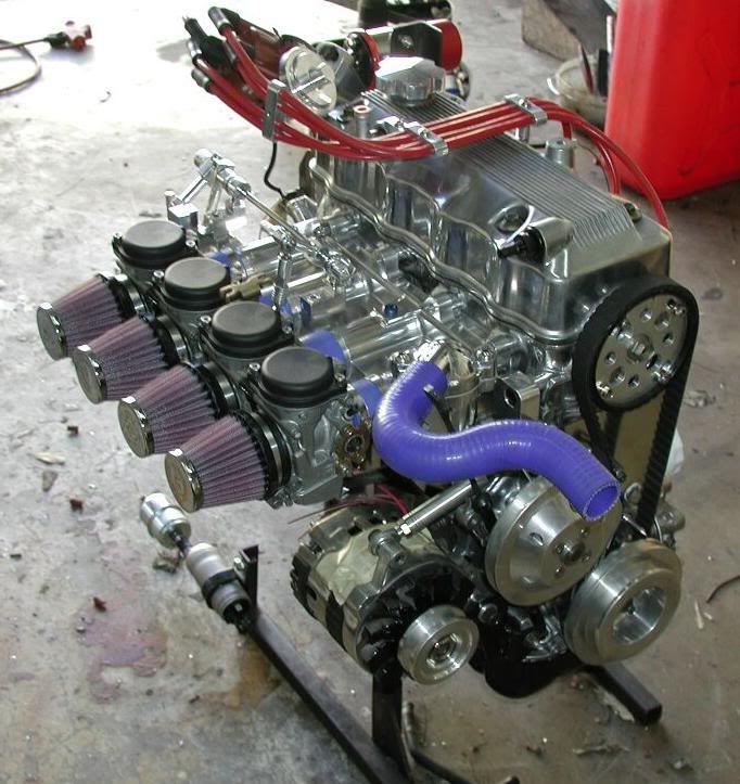
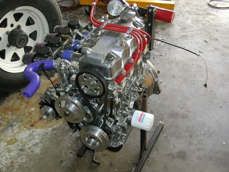
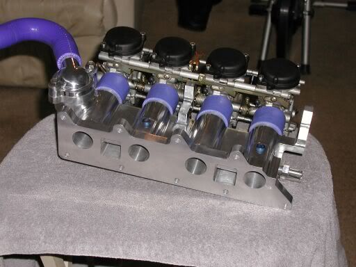
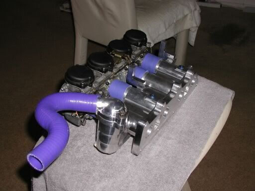
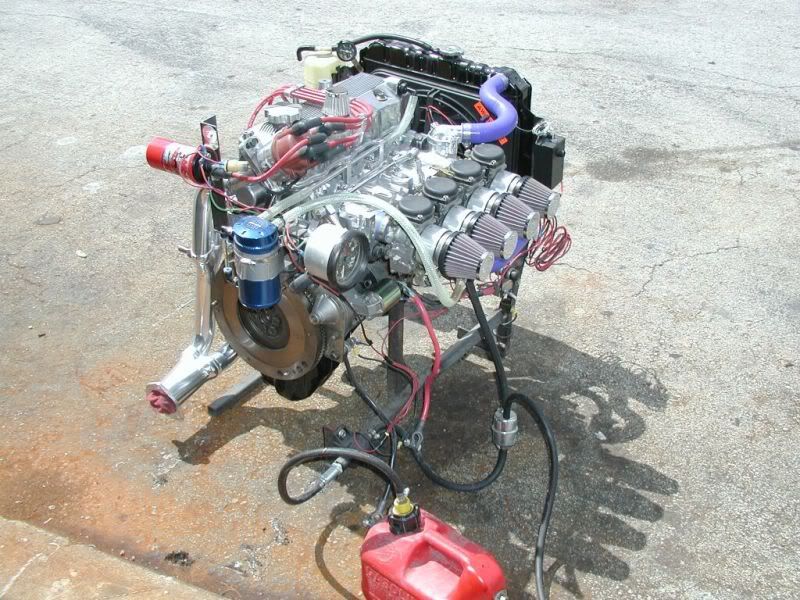
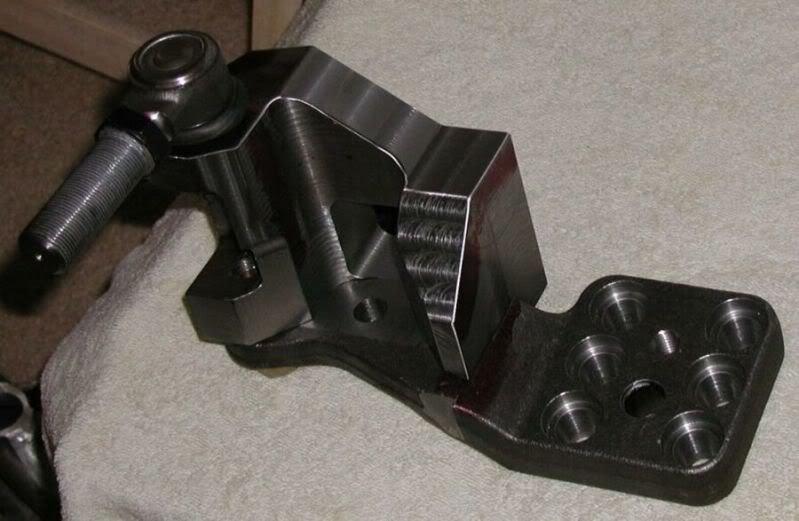
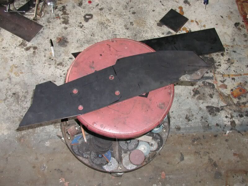
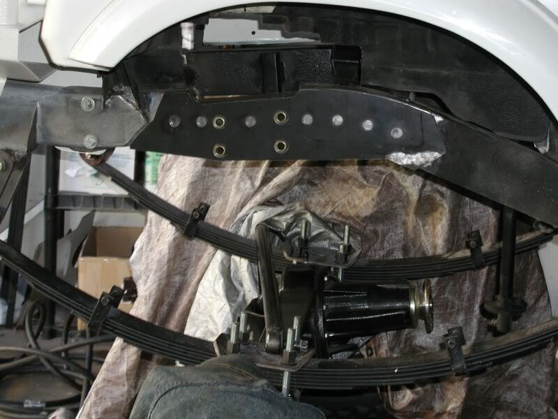
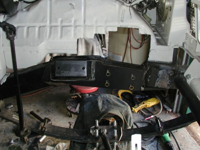
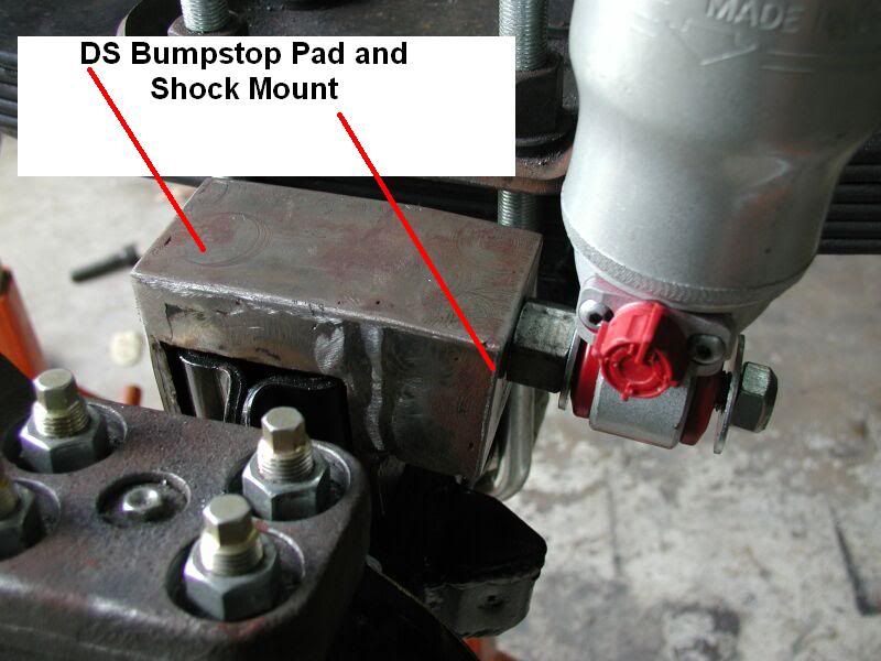
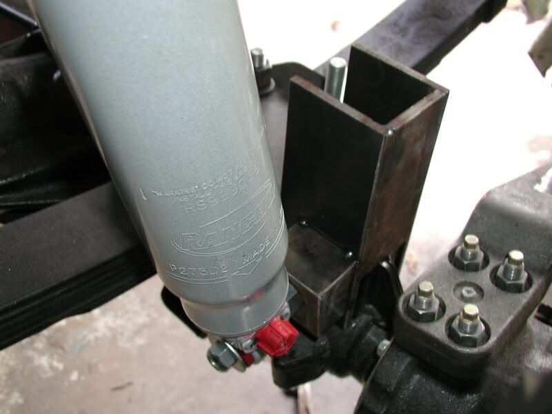
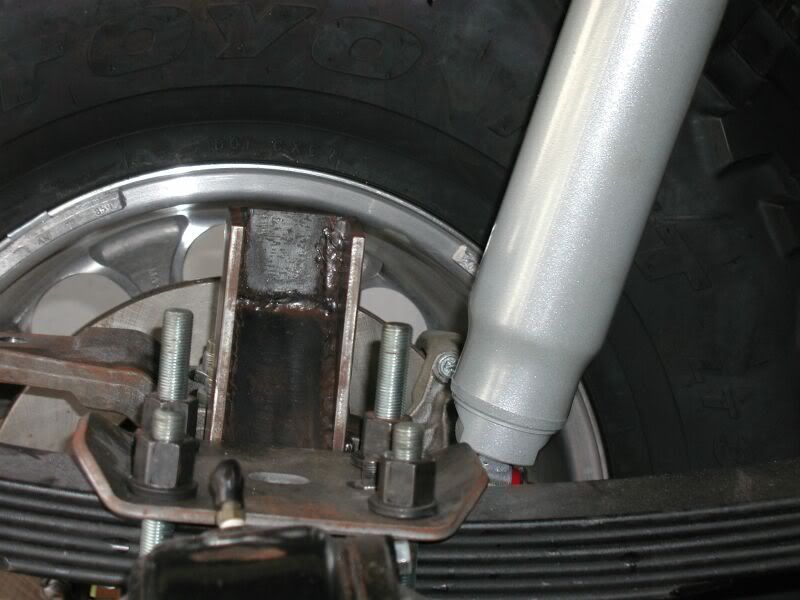
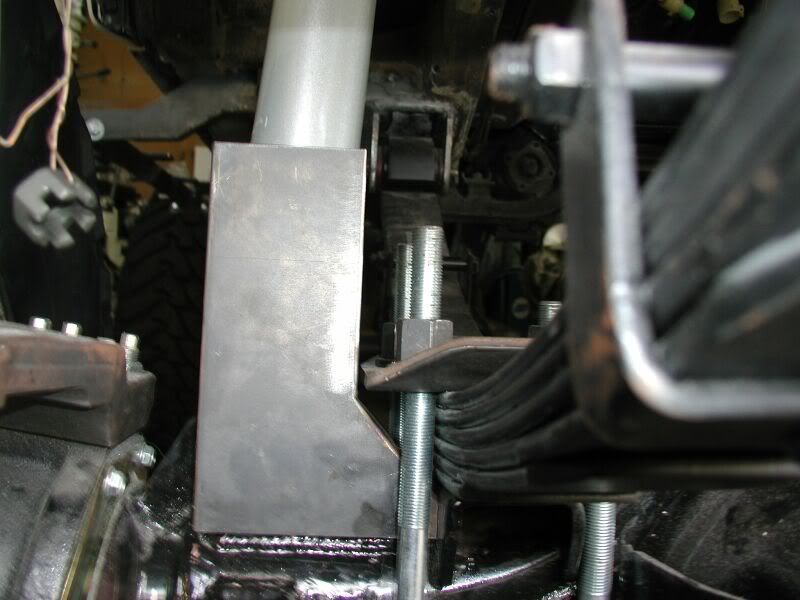
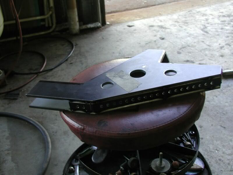
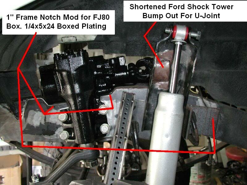
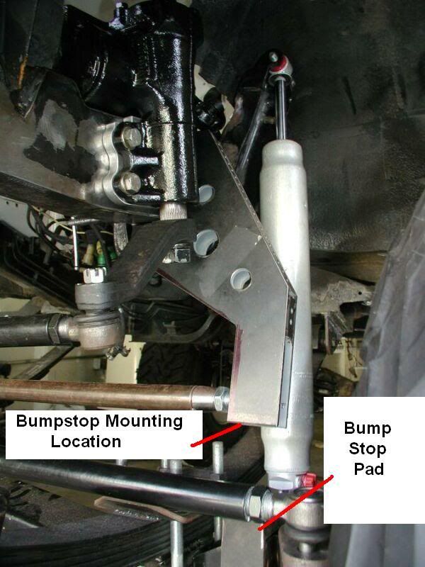
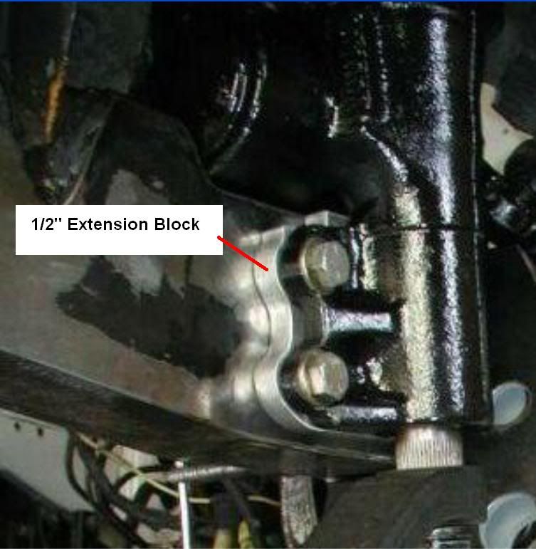
Now if you don’t focus so much on the shiny and purdy stuff. You will notice that I have fabbed quite a few parts for the build and the motor. I also will show in detail how to make and use the some of the parts.

There will also be times that I will share tips and tricks on several things on the Zooks as well. Please be patient and give it some time and you will probably enjoy the build. As I mentioned earlier I have 3 other build threads and they all start off a bit odd but they seem to appreciate the material more and more.

Thanks

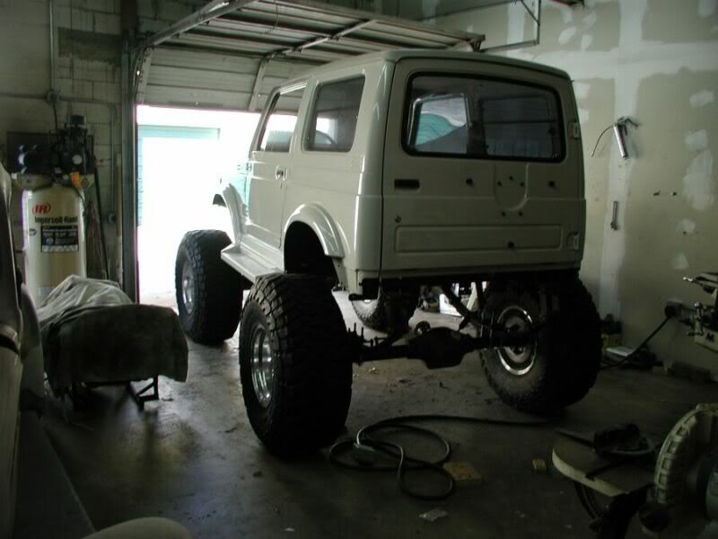
On with the build. I will start with the before and in process pics being the Rig is still being built.


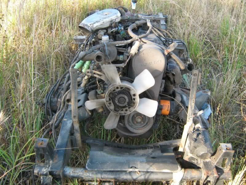
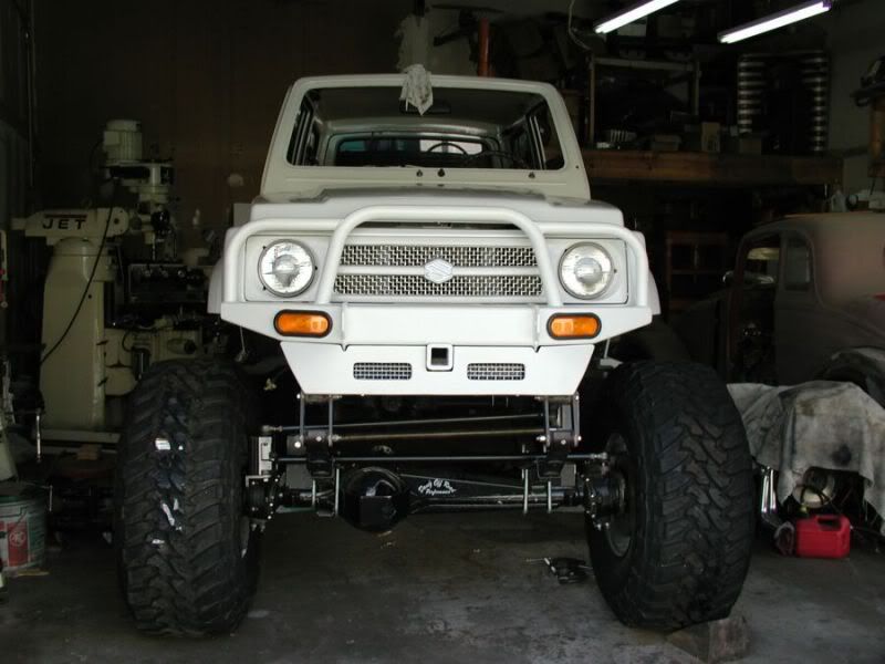
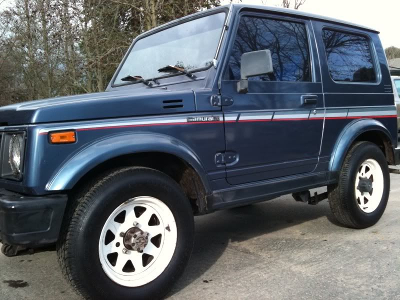
Before completely stock from California

Image


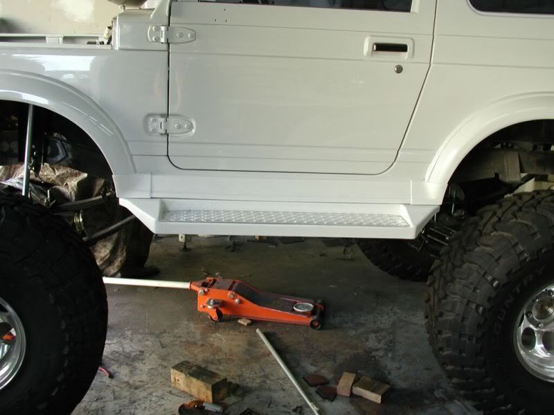
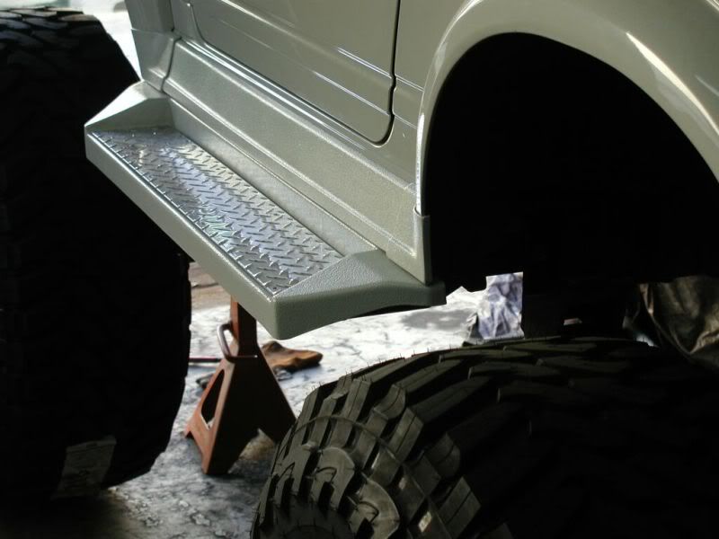
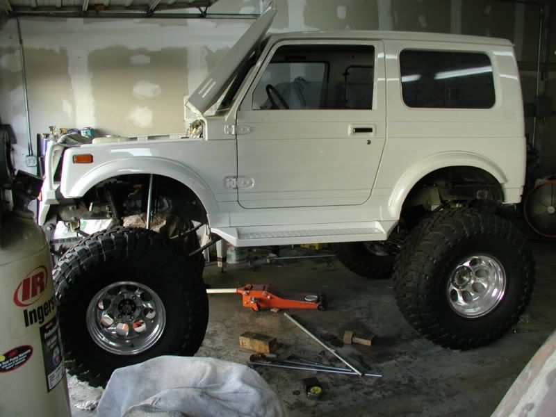
Completely stripped and repainted inside and out.

Image


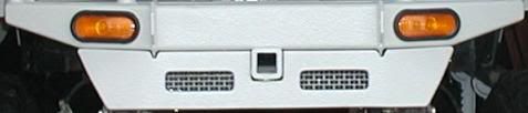
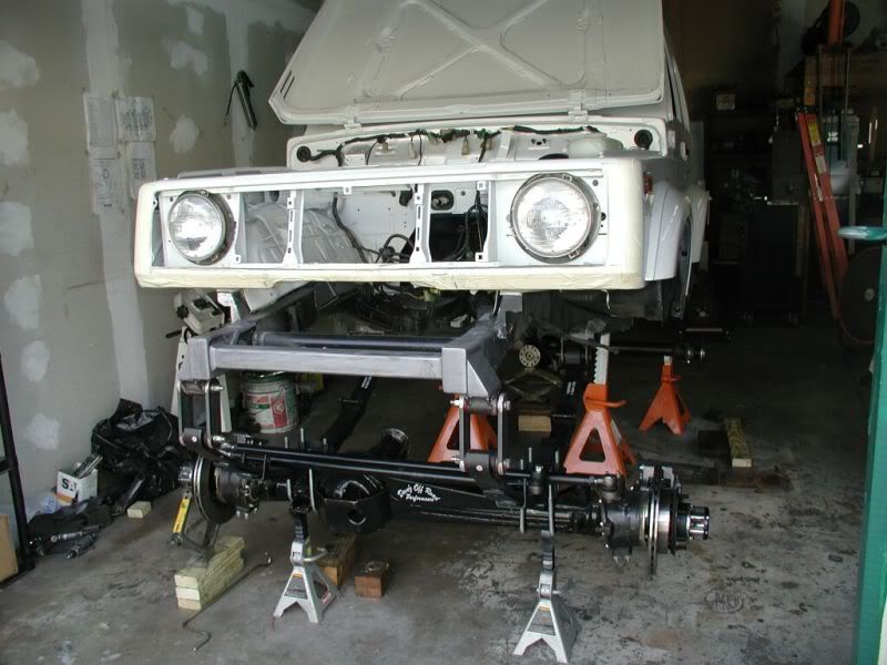
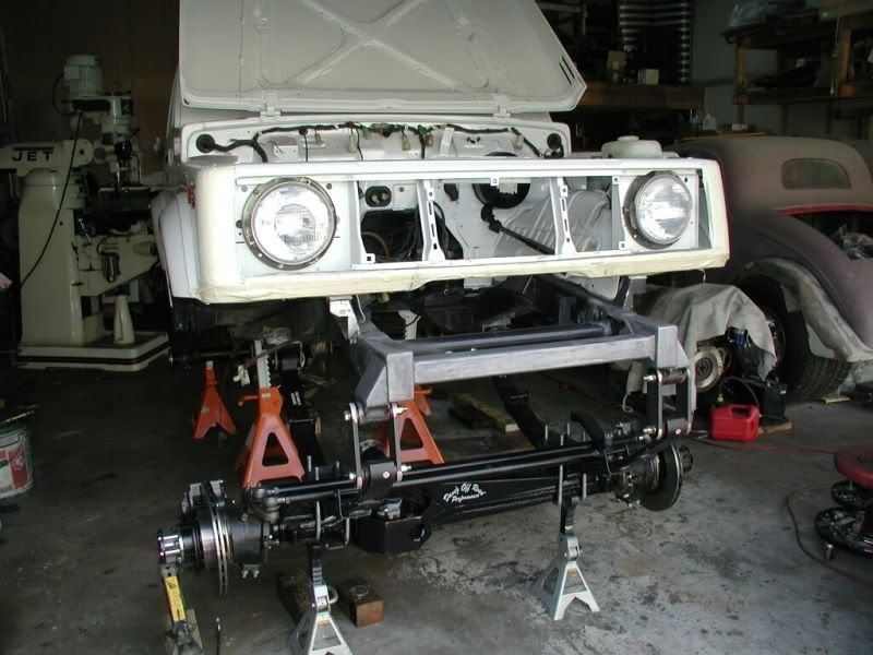
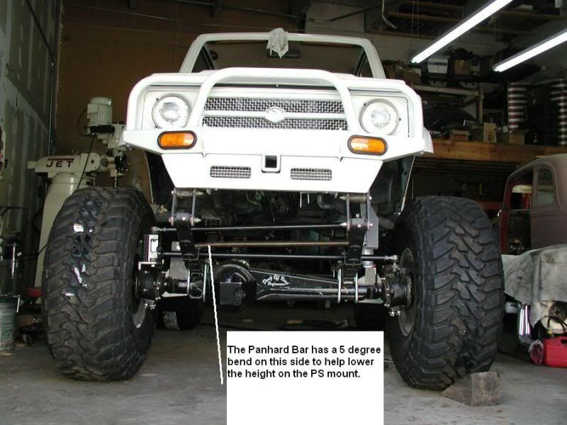
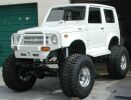
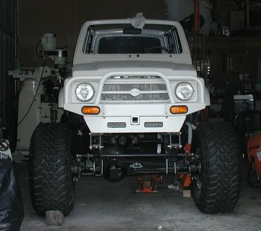
Shrockworks bumper and custom fiberglass valance
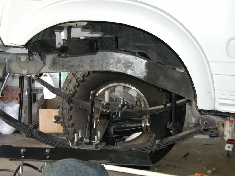
Image


Rear View

Image

User avatar
TanZuk
Engaged 4wd low
Engaged 4wd low
Posts: 234
Joined: Thu Jan 05, 2012 11:17 pm
Location: Pompano Beach, Florida US

Re: Zuk on 38's

Post by TanZuk » Thu Feb 23, 2012 8:40 pm

Here are the suspension and drive train stats:

88" wheelbase, 84 inches tall, 82 inches wide.

Front frame extended 8 inches rear 3 inches

4 1/2 inch YJ lifted springs

Toyo 38's and 16x12 wheels

85 Toy front axle with all Trail Gear inners including Trunion Bearing Eliminator
529 gears open and High Pinion, 6 Shooter Knuckles with High Steer and 1 inch
Space.r

Rear axle is Trail Gear offset Sami Toy housing, 529 gears open and 1.5 spacers,
Rear Disk Brake, Outboard Shocks.

FJ80 steering box, Panhard bar and Rancho 9000 36" length.

ZOR Snatch

6.5 Transfer Case Gears

The trans will also be gone through

No driveshafts yet

User avatar
TanZuk
Engaged 4wd low
Engaged 4wd low
Posts: 234
Joined: Thu Jan 05, 2012 11:17 pm
Location: Pompano Beach, Florida US

Re: Zuk on 38's

Post by TanZuk » Thu Feb 23, 2012 8:42 pm

Here is the motor. I have a machine shop and machined a lot of the parts for the motor.

Here is the Before Pic

Image


After


Image


Image


6061 Aluminum Intake

( This ways a solid block and weighed 35 pounds )

When it was finished it was 8 pounds


Image


Image


********************************************************


Image


Please feel free to click on the link to hear the motor run.


:rockin: http://www.skyscomputers.com/pictures/f ... 0Motor.wmv :rockin:

User avatar
TanZuk
Engaged 4wd low
Engaged 4wd low
Posts: 234
Joined: Thu Jan 05, 2012 11:17 pm
Location: Pompano Beach, Florida US

Re: Zuk on 38's

Post by TanZuk » Thu Feb 23, 2012 8:44 pm

Motor: 1.3 .020 over and deck shaved,


I used dish pistons because of the decking,

1.6 Reynolds ported polished and larger valves and shaved head.

Adjustable timing gear was used because of the shaving of the head and block.

I also had to make a custom timing adjuster wheel. It was too small in diameter and was unable to get the timing belt tight.

Internals are balanced and flywheel,

I'm going to use a Centerforce clutch this time.

The intake was made from a solid block of 6061. It started at 35 pounds when the machining was done it was 8 pounds. I also decided to machine the water ports in the manifold.

The carbs are 32mm Katana GSX-F.

The external accessories on the motor I have also machined up.

The distributor has been switched to mechanical.

User avatar
TanZuk
Engaged 4wd low
Engaged 4wd low
Posts: 234
Joined: Thu Jan 05, 2012 11:17 pm
Location: Pompano Beach, Florida US

Re: Zuk on 38's

Post by TanZuk » Thu Feb 23, 2012 8:45 pm

I also do fiberglass work ( Not By Choice)

After installing the front Shrock Work bumper it looked like it was missing something. I decided to make a lower valance to conceal the 8” frame extension. I’m also getting a bit older and needed an additional step. I decided to make some running boards for the 2nd step. The back tire is being used as the 1st.

The bumpers, fiberglass pieces and the body moldings were Rhino Lined to match the paint for durability.


Front Lower Valance

Image


Side View Running Board

Image


Rear Side View Running Boards

Image

User avatar
TanZuk
Engaged 4wd low
Engaged 4wd low
Posts: 234
Joined: Thu Jan 05, 2012 11:17 pm
Location: Pompano Beach, Florida US

Re: Zuk on 38's

Post by TanZuk » Thu Feb 23, 2012 8:47 pm

Front Frame Extension is 8” and is level to the ground instead of following the frame. I also smooth out all my welds. This tends to add a lot more time to a build just my preference.


Image


Image

User avatar
TanZuk
Engaged 4wd low
Engaged 4wd low
Posts: 234
Joined: Thu Jan 05, 2012 11:17 pm
Location: Pompano Beach, Florida US

Re: Zuk on 38's

Post by TanZuk » Thu Feb 23, 2012 8:48 pm

The Rig is rather high as you can see. This presented some unique problems trying to get the steering geometry setup without a steep angle. I will go through the mods and the parts that needed to be made to correct the problems in the next couple of posts.


I also have an unusual steering set up with the FJ80 box, Lifted YJ springs and the addition of the Panhard bar just to make it more complicated. There is not a great deal of room to work with when you have to add a shock tower in the mix on the DS.


Steering Front View. I still need to do some welding and fitting yet.
The steering geometry is set at 5 degrees.

Image


Panhard Bar was bent at one end to 5 degrees to shorten the PS mounting bracket. I have a 3/4 Heim in the DS and will be using a suspension bushing on the PS. This will help the bar from flopping with the bend in it.

Image


Extended High Steer Arm was made from 8620 the same material the 6 shooter arm is made out of. These pieces will be tig welded together. The block started off at 30 pounds. After several hours of whittling I got it down to a more manageable 9 pounds.

Image

User avatar
TanZuk
Engaged 4wd low
Engaged 4wd low
Posts: 234
Joined: Thu Jan 05, 2012 11:17 pm
Location: Pompano Beach, Florida US

Re: Zuk on 38's

Post by TanZuk » Thu Feb 23, 2012 8:50 pm

To help eliminate one problem:

I started off by dropping the FJ80 box 1” to help decrees the drag link angle. The Frame was notched 1” and the holes filled in the frame before adding the frame plates. This was done to the inside, outside, top, bottom and the notch.

1" Frame Drop Mod

Image


1/4 Outside Drop Plate

Image


Outside plate mounted with DOM bushings and rosset welding holes.

Image


Inside plate mounted

Image

User avatar
TanZuk
Engaged 4wd low
Engaged 4wd low
Posts: 234
Joined: Thu Jan 05, 2012 11:17 pm
Location: Pompano Beach, Florida US

Re: Zuk on 38's

Post by TanZuk » Thu Feb 23, 2012 8:53 pm

Now that I have the FJ80 box mod done. The next issue was mounts for shocks, panhard and bump stops. This took me quite a while to come up with something to incorporate all of this into 2 mounts.

Note:

These mounts were made to sandwich over the TG Shock and Ball support Brackets on both sides.


Driver Side (Side View) Shock Mount and Bumpstop Pad

Image


Passenger Side (Rear View) Shock Mount ,Panhard Bracket and Bumpstop Pad that still needs to be added to the top.

Image


Passenger Side (Side View) Shock Mount ,Panhard Bracket and Bumpstop Pad

Image


Passenger Side (Front View) Shock Mount ,Panhard Bracket and Bumpstop Pad

Image


Drivers Side Frame Panhard Bracket and Lower Bumpstop Mount

Image


NOTE:

Thought I would add that I switched over to the 6 shooters after the pics were taken.

User avatar
TanZuk
Engaged 4wd low
Engaged 4wd low
Posts: 234
Joined: Thu Jan 05, 2012 11:17 pm
Location: Pompano Beach, Florida US

Re: Zuk on 38's

Post by TanZuk » Thu Feb 23, 2012 8:55 pm

This is the side that got to be very congested.


Components:
Fj80 Box
Panhard Bar Bracket
Ford Shock Tower

Mods:
1" Frame Notch
Frame Plating
Bump Out for the Steering U-Joint and Box Plating

Image


Drivers Side Bumpstop Mounting and Pad Locations. There will be additional bracing added to the Panhard Bar Mount for the stress of the Bumpstop Action.

Image


FJ80 Box 1/2 Extension Block. I added this to lengthen the Drag Link. This will also cut down on the angle and decrease the rotational effects of the Panhard Bar.

Note:

The Drag Link length is 37 1/2 inches. Anything over 36 inches is ideal for a Panhard Bar applications.

Image

Post Reply